Shield materials for beta emitters
Stopping a beta is two separate decisions, and only the first one is about thickness. A few millimetres of almost anything will absorb the electrons. What the electrons leave behind on the way is decided by what you chose to stop them with, and that is where lead — the reflex answer for every other kind of radiation — is the wrong material to reach for first.
Thickness follows from the endpoint
The range of a beta is set by the most energetic electrons in the spectrum, not the average ones, so a shield is sized on the endpoint. Rh-106 has the hardest beta in this dataset at 3.54 MeV, and it is stopped by 15.0 mm of acrylic or 6.56 mm of aluminium. Nothing in this dataset needs more than that.
| Nuclide | Endpoint (MeV) | Acrylic (mm) | Aluminium (mm) | Water (mm) |
|---|---|---|---|---|
| Rh-106 | 3.54 | 15.0 | 6.56 | 17.7 |
| Pr-144 | 3.00 | 12.6 | 5.49 | 14.8 |
| Y-90 | 2.28 | 9.28 | 4.06 | 10.9 |
| Ho-166 | 1.85 | 7.35 | 3.22 | 8.68 |
| P-32 | 1.71 | 6.70 | 2.93 | 7.90 |
| Y-91 | 1.54 | 5.95 | 2.60 | 7.02 |
| Sr-89 | 1.50 | 5.75 | 2.51 | 6.78 |
| Co-60 | 1.49 | 5.70 | 2.49 | 6.73 |
| Mo-99 | 1.22 | 4.45 | 1.95 | 5.25 |
| Bi-210 | 1.16 | 4.21 | 1.84 | 4.97 |
The ten hardest beta emitters carried here, of 35. Ranges are Katz–Penfold fits to the endpoint: stopping thicknesses rather than attenuation lengths, good to about ±10%.
Being on that list does not make a nuclide a beta shielding problem. Co-60, Rh-106, Mo-99 are carried here for their endpoint, but in a real source the photon field dominates — Co-60 has an air kerma rate constant of 0.306 mGy·m²/(GBq·h), and a few millimetres of acrylic does nothing about that. For those the beta shield is a secondary detail inside a photon shield, not the shield.
Material follows from bremsstrahlung
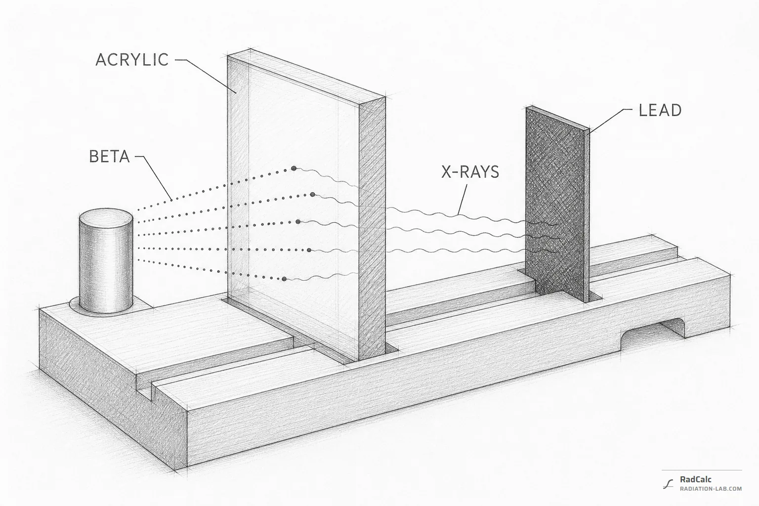
An electron brought to rest radiates part of its energy as X-rays. The fraction rises with the atomic number of the absorber, and it rises with the energy of the electron. Stop a hard beta in lead and a shield that was supposed to remove a short-range, easily absorbed radiation has manufactured a penetrating one in its place, inside the shield, where it is hardest to deal with. Stop the same beta in acrylic and the same conversion happens, but far less of it.
| Nuclide | Endpoint (MeV) | Converted in acrylic | Converted in lead |
|---|---|---|---|
| Rh-106 | 3.54 | 0.74% | 10.16% |
| Pr-144 | 3.00 | 0.63% | 8.60% |
| Y-90 | 2.28 | 0.48% | 6.54% |
| Ho-166 | 1.85 | 0.39% | 5.32% |
| P-32 | 1.71 | 0.36% | 4.91% |
| Y-91 | 1.54 | 0.32% | 4.43% |
| Sr-89 | 1.50 | 0.32% | 4.31% |
| Co-60 | 1.49 | 0.31% | 4.28% |
| Mo-99 | 1.22 | 0.26% | 3.49% |
| Bi-210 | 1.16 | 0.24% | 3.33% |
The ratio between the two columns is 13.7 on every row, and it is the same on every beta emitter in this dataset. That is not a measurement: the yield used here is proportional to atomic number, so the ratio is fixed at 82/6 by the formula itself. What actually varies from nuclide to nuclide is the size of the fractions, which follows the endpoint — from 0.004% to 0.74% in acrylic across the 35 beta emitters here.
Low atomic number first, high atomic number behind
The practical arrangement follows from those two facts. The electrons meet a low-Z absorber first — acrylic, aluminium, or water in a tank — chosen thick enough to exceed the range from the first table. Whatever X-rays that layer does produce then meet a second, thin, high-Z layer placed behind it, where lead is exactly the right material, because photons are what it is good at. Reverse the order and the first layer becomes the X-ray source.
Whether the second layer is needed at all is an activity question rather than a material one. The converted fraction is small: at the hardest endpoint here it is 0.74% in acrylic. At kilobecquerel activities that is nothing. At the tens of gigabecquerels used in industrial sources it is not.
Which endpoint to size on
For 5 of the nuclides here the endpoint in the first table is not the one that decides either answer. Each of them sits above a short-lived daughter with a harder beta, and a source contains both, so both the thickness and the converted fraction have to be taken from the daughter. Nuclides whose daughter sets the shield lists them with the factor by which the parent figure understates the thickness.
Limits of these figures
The converted fractions here come from a thick-target rule of thumb, linear in atomic number and in endpoint energy. It is an order-of-magnitude guide whose purpose is to show why the material matters, and it is not a substitute for a transport calculation: it says nothing about where inside the absorber the X-rays are made, what their spectrum is, or how much of it escapes. The ranges carry their own ±10%. Neither figure accounts for the container the source already sits in, which for a sealed source may be doing most of the work described here before anything is added.
Where to go next
- Beta dose rate and shielding — range, transmission and converted fraction for an endpoint and absorber you choose.
- Nuclides whose daughter sets the shield — the cases where the endpoint above is the wrong one.
- Methods and data — the formulas and where the decay data come from.
- Limits of this dataset — what these approximations do and do not cover.